Serial communication is basically the transmission or reception of data one bit at a time. Today’s computers generally address data in bytes or some multiple thereof. A byte contains 8 bits. A bit is basically either a logical 1 or zero. Every character on this page is actually expressed internally as one byte. The serial port is used to convert each byte to a stream of ones and zeroes as well as to convert a streams of ones and zeroes to bytes. The serial port contains a electronic chip called aUniversal Asynchronous Receiver/Transmitter (UART) that actually does the conversion.

The serial port has many pins. We will discuss the transmit and receive pin first. Electrically speaking, whenever the serial port sends a logical one (1) a negative voltage is effected on the transmit pin. Whenever the serial port sends a logical zero (0) a positive voltage is effected. When no data is being sent, the serial port’s transmit pin’s voltage is negative (1) and is said to be in aMARK state. Note that the serial port can also be forced to keep the transmit pin at a positive voltage (0) and is said to be the SPACE or BREAK state. (The terms MARK and SPACE are also used to simply denote a negative voltage (1) or a positive voltage(0) at the transmit pin respectively).
When transmitting a byte, the UART (serial port) first sends a START BIT which is a positive voltage (0), followed by the data (general 8 bits, but could be 5, 6, 7, or 8 bits) followed by one or two STOP BITs which is a negative(1) voltage. The sequence is repeated for each byte sent.Figure 1 shows a diagram of a what a byte transmission would look like.
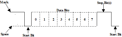
Figure 1
At this point you may want to know what is the duration of a bit. In other words, how long does the signal stay in a particular state to define a bit. The answer is simple. It is dependent on the baud rate. The baud rate is the number of times the signal can switch states in one second. Therefore, if the line is operating at 9600 baud, the line can switch states 9,600 times per second. This means each bit has the duration of 1/9600 of a second or about 100 µsec.
When transmitting a character there are other characteristics other than the baud rate that must be known or that must be setup. These characteristics define the entire interpretation of the data stream.
The first characteristic is the length of the byte that will be transmitted. This length in general can be anywhere from 5 to 8 bits.
The second characteristic is parity. The parity characteristic can be even, odd, mark, space, or none. If even parity, then the last data bit transmitted will be a logical 1 if the data transmitted had an even amount of 0 bits. If odd parity, then the last data bit transmitted will be a logical 1 if the data transmitted had an odd amount of 0 bits. If MARK parity, then the last transmitted data bit will always be a logical 1. If SPACE parity, then the last transmitted data bit will always be a logical 0. If no parity then there is no parity bit transmitted.
The third characteristic is the amount of stop bits. This value in general is 1 or 2.
Assume we want to send the letter ‘A’ over the serial port. The binary representation of the letter ‘A’ is 01000001. Remembering that bits are transmitted from least significant bit (LSB) to most significant bit (MSB), the bit stream transmitted would be as follows for the line characteristics 8 bits, no parity, 1 stop bit, 9600 baud.
LSB (0 1 0 0 0 0 0 1 0 1) MSB
The above represents (Start Bit) (Data Bits) (Stop Bit)
To calculate the actual byte transfer rate simply divide the baud rate by the number of bits that must be transferred for each byte of data. In the case of the above example, each character requires 10 bits to be transmitted for each character. As such, at 9600 baud, up to 960 bytes can be transferred in one second.
The above discussion was concerned with the “electrical/logical” characteristics of the data stream. We will expand the discussion to line protocol.
Serial communication can be half duplex or full duplex. Full duplex communication means that a device can receive and transmit data at the same time. Half duplex means that the device cannot send and receive at the same time. It can do them both, but not at the same time. Half duplex communication is all but outdated except for a very small focused set of applications.
Half duplex serial communication needs at a minimum two wires, signal ground and the data line. Full duplex serial communication needs at a minimum three wires, signal ground, transmit data line, and receive data line. The RS232 specification governs the physical and electrical characteristics of serial communications. This specification defines several additional signals that are asserted (set to logical 1) for information and control beyond the data signals and signal ground.
These signals are the Carrier Detect Signal (CD), asserted by modems to signal a successful connection to another modem, Ring Indicator (RI), asserted by modems to signal the phone ringing, Data Set Ready (DSR), asserted by modems to show their presence, Clear To Send (CTS), asserted by modems if they can receive data, Data Terminal Ready (DTR), asserted by terminals to show their presence, Request To Send (
RTS), asserted by terminals when they want to send data. The section RS232 Cabling describes these signals and how they are connected.
The above paragraph alluded to hardware flow control. Hardware flow control is a method that two connected devices use to tell each other electronically when to send or when not to send data. A modem in general drops (logical 0) its CTS line when it can no longer receive characters. It re-asserts it when it can receive again. A terminal does the same thing instead with the RTS signal. Another method of hardware flow control in practice is to perform the same procedure in the previous paragraph except that the DSR and DTR signals are used for the handshake.
Note that hardware flow control requires the use of additional wires. The benefit to this however is crisp and reliable flow control. Another method of flow control used is known as software flow control. This method requires a simple 3 wire serial communication link, transmit data, receive data, and signal ground. If using this method, when a device can no longer receive, it will transmit a character that the two devices agreed on. This character is known as the XOFF character. This character is generally a hexadecimal 13. When a device can receive again it transmits an XON character that both devices agreed to. This character is generally a hexadecimal 11.
WCSC’s family of serial communication libraries, DLLs, and drivers relegates all the complexities of serial communication to a simple API. Our library eliminates the need for the engineer or programmer to spend valuable time learning the nuances of serial communication and operating specific problems.